Features
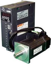
- Smart servo-drive enables stand-aloneoperation!
- Program size up to 1000 steps is available.
Any PLC for simple drive control system is not necessary. - Compact size! Any optionboard is not necessary!
- Various types of Input /Output ports!
- 12 points DI/ 8 points DO/ 2 ports analogue signal input (0-10V). - 24 control commands and 17 motion commands are available!
- Start timing control of multi-axis is also achievable by connecting plural servo drivers with Input / Output ports. - 100 points for positioningcommand and 16 levels for velocity command!
(Available with non-volatile memories.) - Human friendly programminglanguage!
- Easy to generate your program by a language similar to Visual Basic®. - Powerful programming environmentand debugging functions!
- Available on Windows® 95/98/XP.
- Single step execution, control by brake-points, etc. are available. - RS485 interface (Modbus-RTU Protocol) is available!
(Optional module is necessary)
Enhanced programmable function 1
RUN terminal specification
- Servo ON/OFF can be controlled by user program.
- Reset sequence from 'trip' status can be written inuser program and invoked with interrupt on trip.
Simple electrical cam function
Synchronized control to master encoder's speed is easily done. The synchronizing speed pattern can be changed dynamically.
Password function
Protect Reading, Writing, Clearing of program.
Variable electrical gear function
- The electrical gear ratio can be changed from user program.
- Suitable for adjusting to the changing diameter in winding application.
Free Run Timer
Probing function
Re-assignment of I/O terminal by parameter setting
Enhanced programmable function 2
Communication function - RS-485 (Modbus-RTU) (Option)
Low price & Easy system by ADAX4 + RS-485 communication
- Easy connection between EH-SIO & Servo ADAX4-MB & Inverter SJ200/L200 by RS-485.
- Master easily control the start/stop of programmable function, general I/O, and 7-seg LED. Some of the external devices can be saved.
- Programmable Function takes care of the motion control of the drive, which makes the communication of RS-485 be simple.
- Position teaching can be performed with newly lined-up teaching unit, ADOPE-SR.
Control Topics
- Servo ON/OFF
- Change Command
- Monitor status
- Clear Trip
- Read/Write parameters
- Control 7-seg(d-17)
- Remote I/O
Teaching Unit
- Jogging
- Inching
- Teaching points
Example of system : parts picking and placing with force control
Servo-drive withI/O control function can be performed by servo driver only.
- Speed change by micro-switch signal
- Hold position by actual load signal level
- On-line modification of programmed operations via manual switches
Programming Environment
Program editor is available on Windows® 95/98/Me, Windows® NT4.0/2000/XP personal computer system. Data transfer to/from the servo driver is done by RS232C communication.

| Function | Process performed |
|---|---|
| Programming/editing | Program input, editing, saving, loading, and printing |
| Compiling and recompiling | Compiling edited program and Recompiling uploaded program |
| Uploading and downloading | Download/Upload the program to/from servo drive |
| Debugging support | Downloaded program execution, 1-step execution, breakpoint, etc. |
Specifications of Programmable Logic Functions
Other specifications are equal to Standard type Drivers.
| Item | Specifications | |
|---|---|---|
| Language specifications |
Language type | Language similar to Visual BASIC® with additional commands for motion control. |
| Input device | Personal computers (Windows 95/98/Me, Windows NT4.0, Windows 2000/XP) |
|
| Program size capacity |
1000 steps (The drive can store up to 1000 steps) |
|
| Programming support functions |
• Text input • Display on terminal • Program syntax check on terminal • Program loading and all clear (PC -- servo drive) • Single step execution • Breakpoints (up to 4 points) |
|
| Execution method | Interpreter method, 1.12 ms/command (Subroutine calls available, up to 8 nesting levels) |
|
| Input/output functions |
Digital input | Contact signal/open-collector signal input (24V-DC internal power supply provided). servo ON, alarm reset, and general-purpose input (12 points, referred as X(0) to X(11)) |
| Digital output | 8 points (Y(0) to Y(7)) | |
| Analogue output | 2 points (XA(0) and XA(1)) | |
| Reserved words |
Variables | • Position reference: P(00) to P(99) (100 points) • Speed reference: N(00) to N(15) (16 points) • Torque reference: T(00) to T(15) (16 points) • Acceleration time: ACC(0), ACC(1) (2 points) • Deceleration time: DEC(0), DEC(1) (2 points) • Control mode: MOD • Control gain: KSP, KSI, KP, etc. • Monitoring: IFB, IRF, NFB, NRF, POS, PRF, etc. • User-defined variable: U(00) to U(15) (16 points) • Electric cam: MODL, EXD • Driving status: STS • Free-run timer: TIMER1 • Capture: PRB1H/L, PRB2H/L • Generic parameter: OPO~OP3 • Electric gear: EGRAN/EGRAND • Speed command gain: SPDG |
| Commands | Instruction Mnemonic for program control command and motion control command (servo operation command) | |
| Other | Program storage | • Stored in the main unit's EEPROM • Stored as source files and intermediate code files |
| Breakpoints | Up to 4 points (set, reset, enable, or disable) | |
Example of Applications and sample program
Case: Multistage Positioning (Input Terminal Conditions)
- Case description
- Terminal connection
- Timing diagram
- Program example