- Loading
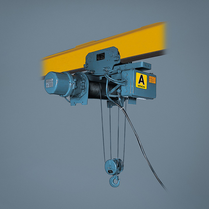
Crane Systems and Related EquipmentRope Hoist: A Series Low Headroom Type
Specifications
Standard Specifications
| Electric Source |
3-Phase 200V 50/60Hz, 220V 60Hz, 380V to 400V/415V 50Hz, 400 to 440V 60Hz |
|---|---|
| Operation Method | Operating push button |
| Electrical Protection | IP44 |
| Ambient Temperature | −10~40°C |
| Humidity Range | 90% or less (No condensation) |
| Power Feeding System | Cable feeding No cable included with standard shipment. |
| Approval | JIS C9620, Japanese Industrial Standard |
| Color (Munsell color) | Munsell 2.5B2.5/1 |
Power Feeding Method and Push Button
| Type | Power Feeding System | Indication |
|---|---|---|
| Suspension type, manual or chain driven trolley | 2points |


|
| With motorized trolley | 6points |


|
Max. number of starts per hour and duty factor
Number of Starts: Less than 250 starts/h
Duty Factor: Less than 25%
- Number of starts include no. of inching
Calculate the Duty Factor with the following formula.

- Trolley and hoist are shipped separately in case of manual or chain driven trolley
Low Headroom Type
| Capacity(ton) | 1 | 2 | 3 | |||
|---|---|---|---|---|---|---|
| Hoisting lift(mm) | 6 | |||||
| Hoisting | Speed(m/min) | 50Hz | 7 | 6 | 5 | |
| 60Hz | 8.4 | 7 | 6 | |||
| Motor | (kW) | 50Hz | 1.2 | 2.1 | 2.6 | |
| 60Hz | 1.5 | 2.4 | 3.1 | |||
| Number of Poles | 4 | |||||
| Traveling | speed(m/min) | 50Hz | 21 | |||
| 60Hz | 25 | |||||
| Traveling motor | (kW) | 50Hz | 0.30 | 0.30 | 0.45 | |
| 60Hz | 0.36 | 0.36 | 0.55 | |||
| Number of Poles | 4 | |||||
| Wire Rope | Number of Falls | 4 | ||||
| Composition | 6X W(19)-B |
6XFi(29)-B | ||||
| Diameter(mm) | Ø6.3 | Ø8 | Ø10 | |||
| Rating | 25%ED 250starts/h | |||||
| Operating method | Floor-controlled Pushbutton operation | |||||
| Electric source(3-phase) | 220/380~415V 50Hz | |||||
| Control voltage(V) | 24~27 | |||||
Dimensions
- Images of the representative models, '1-ton and 2,3-ton.
With Motorized Trolley
| Model | 1AL-T55 | 2AL-T55 | 3AL-T55 | |||||||||||||
|---|---|---|---|---|---|---|---|---|---|---|---|---|---|---|---|---|
| Hoist type | 1AL5 | 2AL5 | 3AL5 | |||||||||||||
| Trolley type | 1T5 | 2T5 | 3T5 | |||||||||||||
| Capacity(ton) | 1 | 2 | 3 | |||||||||||||
| Approx. dimensions (mm) | L | 6,000 | 6,000 | 6,000 | ||||||||||||
| H | 425 | 515 | 600 | |||||||||||||
| A | 600 | 655 | 705 | |||||||||||||
| B | 475 | 545 | 585 | |||||||||||||
| W | 200/290 | 200/290 | 230/310 | |||||||||||||
| E | 420 | 365 | 400 | |||||||||||||
| F | 375 | 480 | 575 | |||||||||||||
| Ød | 45 | 56 | 71 | |||||||||||||
| J | 28 | 42 | 46 | |||||||||||||
| Y | — | 625 | 620 | |||||||||||||
| ØP | 96 | 96 | 128 | |||||||||||||
| a | 23 | 36 | 42 | |||||||||||||
| Min. curve radius(m) | 1.5 | 1.8 | 2.0 | |||||||||||||
| Dimensions with respect to l-beam(mm) |
S | T | U | C | G | S | T | U | C | G | S | T | U | C | G | |
| 200 × 100 × 7 | 42 | 148 | 52 | 135 | 374 | 42 | 150 | 32 | 135 | 378 | ||||||
| 250 × 125 × 7.5 | 67 | 151 | 49 | 185 | 387 | 67 | 153 | 29 | 185 | 391 | 52 | 177 | 28 | 180 | 417 | |
| 300 × 150 × 11.5 | 92 | 160 | 40 | 225 | 400 | 92 | 163 | 19 | 225 | 404 | 77 | 187 | 18 | 220 | 430 | |
| 450 × 175 × 11 | 102 | 185 | 20 | 370 | 443 | |||||||||||
| Approx.weight(kg) | 180 | 270 | 370 | |||||||||||||
| Push-button indication | ||||||||||||||||
- Dimensions W are for the drive side/driven side.
- Unless otherwise specified, trolley is being assembled so as to meet smudged I-beam size.
Features
- Assembly and disassembly are easy.
- Maintenance and serviceability are improved.
(1) Inspection Window for Gears
It is possible to check the condition of the gear teeth surface and lubrication with eyes.
Inspection accuracy will be increased.
(2) Reduction Gear Unit
A grease lubrication system is adopted. The hoist is greased prior to shipment and requires no grease replenishment during operation, ensuring a long period of utilization. The innovative building block system facilitates maintenance and checking.
(3) Auxiliary Brake Unit
Should the braking force of the main braking system fails or the motor shaft breaks, the newly developed auxiliary brake prevents the load from dropping. In conjunction with the brake with automatic adjusting device, this auxiliary braking device constitutes a positive, double-braking mechanism.
Auxiliary Brake Unit
USA PAT No.4216848
(4) Steel Drum and SheaveNEW
Life of the drum for 2 falls and 4 falls (2 ton and 3 ton), and the sheave is about three times longer than conventional company products, since the groove of them are processed by special press method.
(5) Control BoxNEW
Counter for Memorizing Starting Times
The counter which indicates the total starting times of hoisting and lowering is useful for maintenance of the consumable parts like electromagnetic contactors, wire rope and brake solenoid, etc.
Electro-magnetic Switch with Mechanical Interlock
Erroneous operation can be prevented.
Double-limit Switch
When the load block has reached the upper limit, the control circuit of the electro-magnetic switch is turned off and the operation is stopped. Should the circuit be short-circuited and the load block be moved further upward, the motor main circuit is cut off.
Clamp Method
Clamp method of the control box cover facilitates opening and closing.
(6) Motor Unit
Each hoist is equipped with a motor which provides an optimal starting torque for the hoist and B class insulation. Employing cooling fans and large-capacity ball bearings, the motor can withstand severe operating conditions. Hoisting motor is provided with a thermal protector which senses the heat of the motor coil and functions to protect the motor from burning damages caused by over work.
(7) Brake Unit
The brake is equipped with automatic adjusting device, and is automatically adjusted in proportion to the amount of lining abrasion. Adjustment of the brake will not be required.
Brake Unit with Automatic Adjusting Device
USA PAT No.3908802 Germany PAT No.2354044
Thick Wire Rope
The wire rope features a long life.
Rope EndNEW
Inspection of the Rope End has been easy.
HookNEW
Punch Mark
Punch Mark shows the reference point of hook inspection.
Load Block Fitted with Safety Lever
The load block is provided with a safety lever (to prevent rope from dislodging) in addition to a safety cover.
Integrated Pushbutton Cable
The pushbutton cable and protective wire are built into a single assembly so that there will no longer be a broken wire by hooking the protective wire. This design also assures ease of pushbutton operation.
User-friendly Pushbutton
The push button is totally enclosed type and is made of plastic.
It is light and easy to use without the danger of electric shock.

Catalog Lists and Inquiries
Contact us for inquiries about our products, quotations, and catalog downloads.